| Maximum
Gauge for
Mild Steel |
PANEL DIMENSIONS |
|
PART NO. |
DESCRIPTION |
REQUIRED
PULLER |
| A
Mounting
Hole Dia. |
B
To Prevent
Rotation |
|
|
|
| in. |
mm. |
in. |
mm. |
| 16 ga. |
.375 |
9,5 |
.330 |
8,4 |
1333 |
SRP 375-330 |
1350* |
| .345 |
8,8 |
1334 |
SRP 375-345 |
| 14 ga. |
.437 |
11,1 |
.390 |
9,9 |
1335 |
SRP 437-390 |
1351* |
| .500 |
12,7 |
.450 |
11,4 |
1337 |
SRP 500-450 |
| .460 |
11,7 |
1339 |
SRP 500-460 |
| .465 |
11,8 |
1340 |
SRP 500-465 |
| .562 |
14,3 |
.530 |
13,5 |
1341 |
SRP 562-530 |
| .625 |
15,9 |
.550 |
14,0 |
1342 |
SRP 625-550 |
| .750 |
19,1 |
.660 |
16,8 |
1344 |
SRP 750-660 |
| .875 |
22,2 |
.770 |
19,6 |
1345 |
SRP 875-770 |
1352** |
| .840 |
21,3 |
1346 |
SRP 875-840 |
| 1.000 |
25.4 |
.875 |
22,2 |
1336 |
SRP 1000-875 |
| 1.093 |
27,8 |
.970 |
24,6 |
1338 |
SRP 1093-970 |
| 1.000 |
25,4 |
1347 |
SRP 1093-1000 |
| 1.109 |
28,2 |
1.000 |
25,5 |
1343 |
SRP 1109-1000 |
1353** |
| 1.130 |
28,7 |
1.005 |
25,5 |
1348 |
SRP1130-1005 |
*May be operated manually or used with a hydraulic puller.
**For use with CYL-201 and CYL-205A cylinders. May also be compatible with other industry standard pullers
having a 3/4"-16 socket.
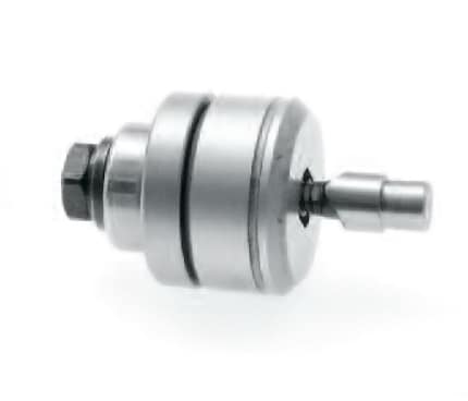
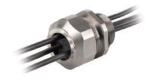
Operating Instructions for Heyco® Strain Relief Mounting Hole Punches
A. Drill hole in panel one size larger than the stud of the punch.
B. Disassemble punch and insert stud through hole.
C. Install die and backing plate onto shaft then bearing and nut.
D. Line up punch shaft to desired position and turn nut until punch goes through the metal.
E. Disassemble nut bearing and backing plate and remove the slug from the die.
F. Repeat process on next hole.
G. ALWAYS REMOVE SLUG AFTER PUNCHING!